IMP Magicbox: Difference between revisions
Jump to navigation
Jump to search
OPENING YOUR RADIO IS AT YOUR OWN RISK!!
No edit summary |
No edit summary |
||
| Line 15: | Line 15: | ||
* 7. Tricky part: gently pull out the two brown pieces of plastic on the flatcable connector until they click. The cable can now be pulled out. | * 7. Tricky part: gently pull out the two brown pieces of plastic on the flatcable connector until they click. The cable can now be pulled out. | ||
* 8. The main PCB can now be pulled out of the radio. | * 8. The main PCB can now be pulled out of the radio. | ||
= PCB's = | |||
The AE is built on 3 PCB's | |||
== Main PCB == | |||
<table><tr> | |||
<td>[[Image:imp_main_top.jpg|thumb|Main PCB top view]]</td> | |||
<td>[[Image:imp_main_bottom.jpg|thumb|Main PCB bottom view]]</td> | |||
</tr></table> | |||
== Amplifier PCB == | |||
The bottom PCB holds a [[WM872]] DA converter and integrated amplifier IC. | |||
<table><tr> | |||
<td>[[Image:imp_amp_top.jpg|thumb|Amplifier PCB top view]]</td> | |||
<td>[[Image:imp_amp_bottom.jpg|thumb|Amplifier PCB bottom view]]</td> | |||
</tr></table> | |||
=== Button PCB === | |||
<table><tr> | |||
<td>[[Image:imp_button_top.jpg|thumb|Button PCB top view]]</td> | |||
<td>[[Image:imp_button_bottom.jpg|thumb|Button PCB bottom view]]</td> | |||
</tr></table> | |||
Revision as of 20:53, 8 November 2006
Opening the IMP
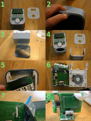
This page describes how to open the IMP radio. Most is easy, but take care when removing or connecting the flatcable, this is a fragile part of the radio's guts.
- 1. Remove the top cover by removing the 4 screws
- 2. Peel of the rubber foot of the radio.
- 3. Underneath are 3 small screws. Remove those.
- 4. Remove the 3 small screws on the top, holding the front cover. Shift of the front
- 5. Remove the 4 scres holding the top PCB. This reaveals 2 larger screws underneath, remove as well
- 6. The front can now be separated from the back. Take care of the speaker cable when opening.
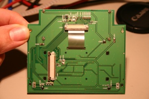
- 7. Tricky part: gently pull out the two brown pieces of plastic on the flatcable connector until they click. The cable can now be pulled out.
- 8. The main PCB can now be pulled out of the radio.
PCB's
The AE is built on 3 PCB's
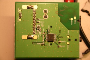
Main PCB
Amplifier PCB
The bottom PCB holds a WM872 DA converter and integrated amplifier IC.


