JTAG Port
Diagnostic
Presently, a possible location for the JTAG port has been identified, but which pin is which has not.
JTAG consists of 4 or 5 pins:
- TRST - A Reset line, which could be tied low via an R, permanently disabling the JTAG interface.
- TDI - Data In
- TDO - Data Out
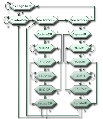
- TMS - The Mode Select pin, which actually drives the JTAG TAP Controller around a simple state machine.
- TCK - Clock
And Is Driven by a State Machine
Pin identification without risk of re-programming
TDO will have to be identified by impedence / voltage level testing.
The last two bits of the instruction register are always 01, so by shifting out the instruction register, activity should be seen on TDO.
TCK: Burst Clock for period of test TDI: 000000000000000000 .... TMS: 011111011000000000 ...
TDI & TMS Change on TCK falling. The '11111' of TMS forces the state machine to reset The '01100' of TMS forces it into the Shift-IR state The '00000000' of TMS forces the TDI in, and the Current Instruction Out
If the inputs pins are connected incorrectly at all, the worst that can happen is '0' can be clocked into TMS twice, which should force the machine to stay in it's Run-Test/Idle state.
If the input pins are connected correctly, some data should be seen on TDO.
